|
ME405: Mechatronics
Project Documentation and Portfolio by Neil Patel
|


|
|
ME405: Mechatronics
Project Documentation and Portfolio by Neil Patel
|
|
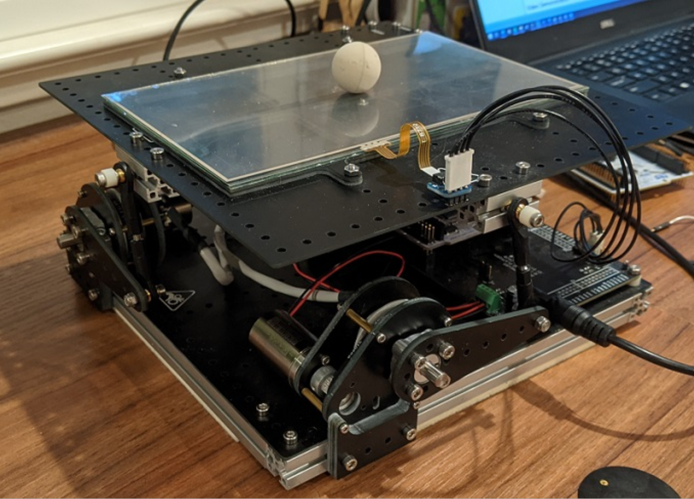
The objective of this lab is to create a culminating term project that utilizes mechatronics and control skills by balancing a ball on top of our mechatronics kit. This project builds upon the system modelling and calculations done in HW0x02, HW0x04, and HW0x05. The project was broken into segments that dealt with assembling separate parts and task, and then integrating them to achieve functionality.
The individual parts that made up the system were the Touch Panel, Motors, and Encoders. The model of the platform was used to build the Controller, which relies on the ball's position data (X,Y) from the touch panel and the motor angle data (theta_X, theta_Y) from the encoder, as well as their derivatives velocity and angular velocity. The final step to the project was to run all 4 segments together. This required a Scheduler to make sure all tasks ran cooperatively. Much of this was done through cotask.py which was provided by the instructor for this class. To easily share data (such as position and angle measurements), a second provided module called task_share.py was used.
The Touch Panel Sensor's purpose is to determine the x and y position of the ball on the platform.
By controlling four pins (Two in the "X" direction and two in the "Y" direction), the distance in mm from the origin (the center of the panel) can be found. There are 3 primary functions to the Touch Panel Driver:
The scan_ALL() function can be used to conveniently perform all 3 measurements. More documentation can be found at touchPanel.py.
The Resistive Touch Panel works by having two wires that wind back and forth from on side to the other side of the panel. One wire's resistance only increases by a noticeable amount in the X direction, while the other only in the Y direction. If you were to look at a point 2/3 of the way through the panel, then 2/3 of the resistance of the wire is before that point, and 1/3 after. When the touch panel is touched, the wires short together at that point. This allows the position of the touch to be measured. Each direction is measured individually by setting one side of the wire for that direction to 3.3 V, and the other to ground. The wire that is not being measured is connected to an ADC on one side while the other side is allowed to float. This allows the voltage at the intersection to be measured, which can be used to determine the position in that direction thanks to the linear increase of the wires resistance. To determine if something is touching the panel at all, one wire has one end connected to 3.3 V, while the other has one end connected to 0 V. If the other end of the 0 V connected wire is measured to also be 0 V, then the wires cannot be connected together, so the panel is not being touched. If the value read is nonzero, then the wires must have been connected and the panel was touched.
A simplified circuit diagram for the touch panel is shown below. The pins (Yp, Ym, Xp, Xm) in this case are configured for scan_Z - determining if the panel is being touched.
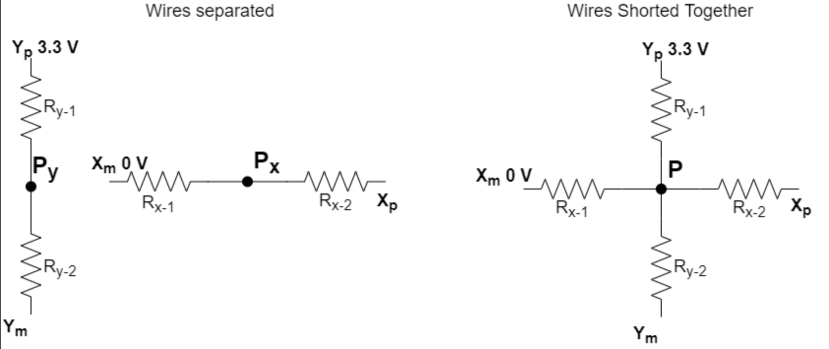
When the touch panel is not being touched, the two wires are not connected to each other, and in this case Xp is tied to 0 V while Ym is tied to 3.3 V. When the panel is touched at point P, the two wires intersect. Since Xp is no longer 0 V and Ym is no longer 3.3 V, we can determine that the touch panel is detecting something. To find the position itself, we just find the Voltage at point P - the position in each direction will be the Voltage at point P as a percent of the input voltage multiplied by the total length of the panel in that direction.
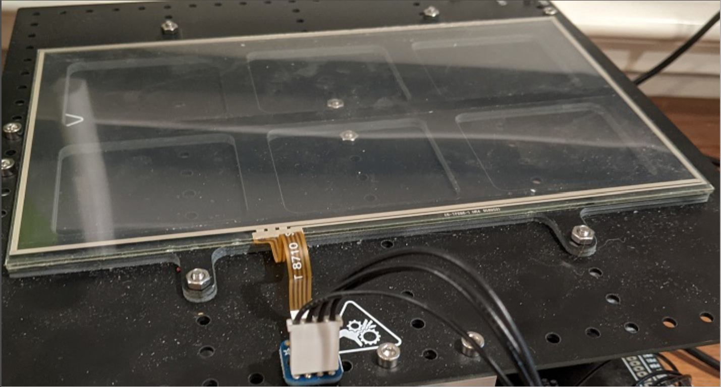
Below is an image of the touch panel on the platform, with nothing touching it. This was used to test the scan_Z function in the benchmarks.
Below is an image of the touch panel on the platform, with the ball that it senses on top. This is the position used to measure the benchmark data.

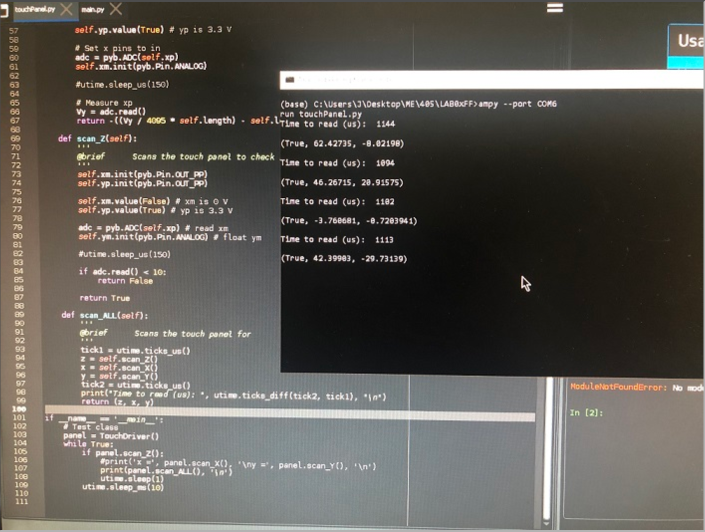
Below is an image of the output of the functioning TouchPanel in PuTTY, including the scan_ALL and the total time for each operation.
The Panel dimensions were found to be 192mm x 112mm. However, measurements did not always function on the border, so the possible measurement ranges are below:
The minimum and maximum Y values likely differ since the panel is slightly off center in the Y direction - there is an extra couple millimeters of dead space on the negative y side to give room for the wires used to connect it to the MCU. As a result, the measured center is slightly above the center of the panel, by about 3 mm. Otherwise, the center measurement was found to be spot on - within a millimeter at least, though I lack the measurement tools to determine its exact position. However, measurements further out from the center became much less accurate, since the resistance of the panel did not seem to be linear.
Each function was tested by running it 50 times in the benchmark. Timing was done using the ticks_us function from the utime library.
With the ball off of the platform:
With the ball on the platform:
With the ball on the platform at around Y = -28mm:
With the ball on the platform at around X = 20.7mm:
Testing all three functions together in the scan_ALL() function:
All three basic scan functions meet the required specs: they all measure under 500 microseconds individually. As a result the scan_ALL() function can be performed in about 1.1 ms, which is easily faster than the estimated 1.5ms needed for the system to function smoothly. Both X and Y measurements were accurate across many trials, with only small variations. The X measurements varied more than the Y measurements most likely because the X axis is longer. The scan_Z() function was equally consistent in identifying if the ball was in contact with the touch panel.
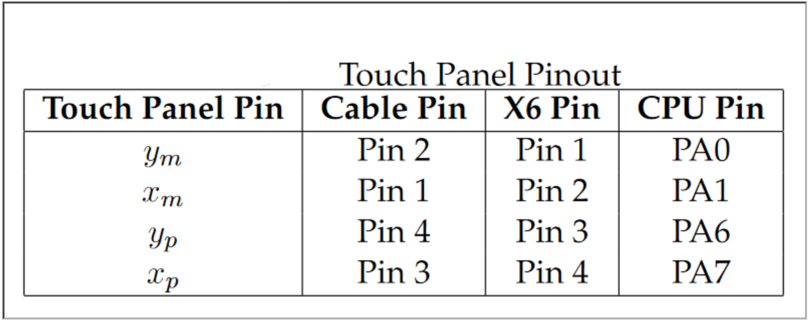
To use the touch panel with the driver, initialize an object for the class and assign the correct pins for each input. For example, if yp from the panel is connected to the PA6 pin on the MCU, then use yp=pyb.Pin.board.PA6 when initializing. Then, scan_Z() can be used to check if something is touching the board before finding the position by calling scan_X() and scan_Y(), and then scan_ALL() can be used to conveniently check all three - it will return a tuple with (Z, X, Y).
The Motor Driver allows the DC motors to be driven at different power levels using PWM.
The user can specify the Duty cycle for each motor. If a fault occurs (such as when something is blocking the motor) the motor will automatically be disabled. It can be re-enabled with clear_fault(). The motors can also be enabled or disabled with enable() and disable() respectively. Upon initializing the driver, takes the pins of the motor as well as the fault and sleep pins. Documentation can be found at motor.py.
Below is an image of the two motors. To set dutycycle, use set_level_1() for Motor 1 and set_level_2() for motor 2. Duty cycle is used as a percent not a decimal.
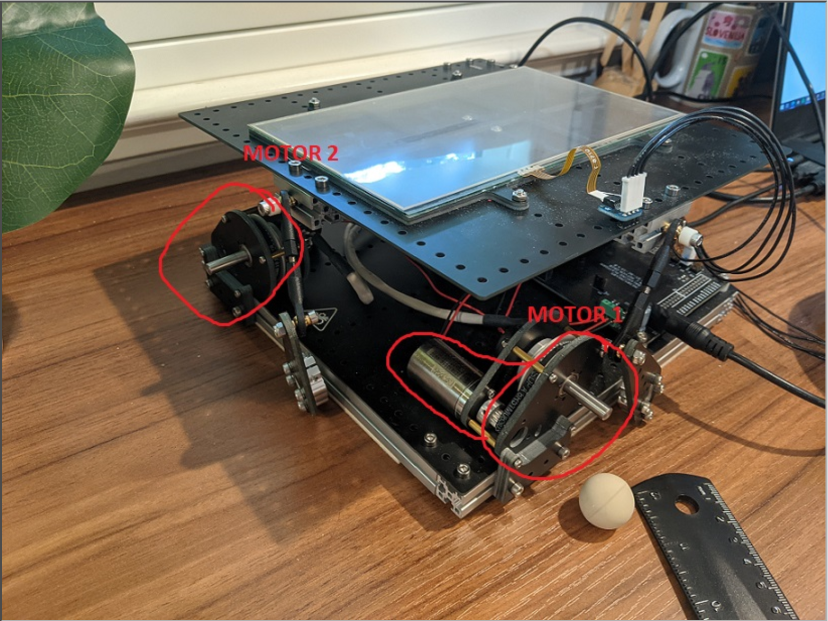
Each motor has 2 inputs to control direction and torque. The two motors share the input nSLEEP, which tells the motors when not to sleep. They also both share the fault pin, nFAULT, which goes low whenever a fault occurs in one of the mots and must be cleared before operation may continue. The affect of the inputs on motor operation is shown below.
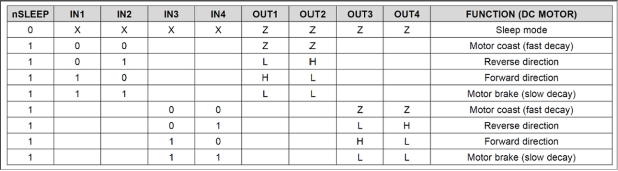
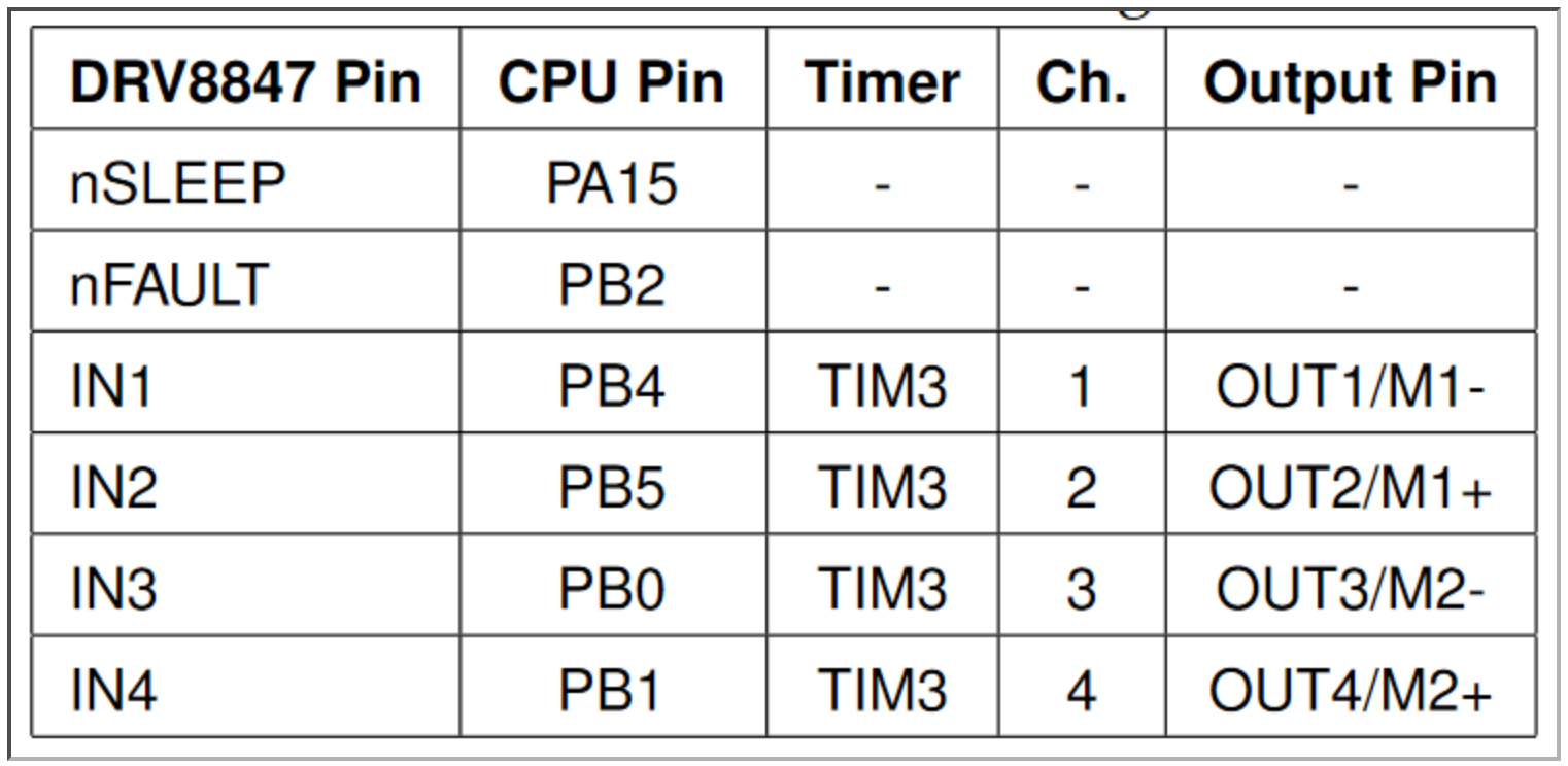
The motors spin when one input is high and the other low. With constant input voltages, the motors behave in an on or off manner In order to adjust the power of the motor, Pulse Width Modulation (PWM) was used. This allowed the dutycycle of the input wave to be adjusted. At 100% duty cycle, when the wave is just a dc constant, the motors operate at full power. By decreasing the percent of time the wave is high compared to low, the power delivered to the motors can be decreased. The motor pins and their corresponding pins on the board are shown below. IN1/IN2 correspond to Motor 1, while IN3/IN4 correspond to Motor 2. The inputs are connected to a Timer for PWM.
Below is a demonstration of motor 1 in action. It is being started at 0% duty cycle and the duty cycle is increased by 1% every half second, until it reaches a duty cycle of 100%. At that point a fault is triggered by forcefully grabbing onto the motor, and the motor stops. (Note: the motor is grabbed before it reaches 100%, so it does not trigger a fault at first).
To test the minimum duty cycle needed for the motors to overcome static friction and begin spinning, each one was set to 0% duty cycle, and then duty cycle was increased in intervals of 1% until the motor began moving consistently.
For Motor 1:
For Motor 2:
The Encoder Driver is used with the encoders to update the angle / angular velocity of the motors.
Like with the motors it initializes with the pins that connect to the encoders. The Encoder Driver class includes a method for updating the current position of the motor with update(), and a separate method for retrieving the current position (get_position()). There is also a method for the change in angle from the previous update (the angular velocity) and one to manually reset the current angle to a chosen value. Documentation can be found at encoder.py.
The encoder driver automatically handles overflow (or underflow) by noting that if the tick count for the encoder has changed by over half its possible values, then it most likely has reached overflow, and then compensating by adding or subtracting 65535 (the total number of ticks in the encoder measurement).
To test that the encoders were working, the platform was tilted back and forth. The tick counter adjusted with the platform and increased in one direction but decreased in the other. From the starting position, it was possible to reach a negative position which indicated that the underflow was working correctly. Since overflow works similarly but in the opposite direction, it was assumed that overflow would also work fine. The video below demonstrates the usage of one of the encoders while tilting the platform. The data can be seen listed in the terminal - the units are ticks, and there are around 4000 ticks to a rotation on the encoder. Apologies for the vertical format.
The Encoder pins are attached as described in the table. The pins they are connected to are connected totimers which support encoder functionality. These are necessary since the timing for encoders is too sensitive to do using pure software.

The Controller object uses the input data of position, theta, velocity, and angular velocity to determine the correct duty cycle for the motor according to the system model.
When instantiating, it takes the K constants from HW0x05, [k1 k2 k3 k4] as arguments. The controller needs to be defined in both the x and y direction - each controller takes one set of inputs and controls one motor. The only method in this class is DutyCycle(x, theta, x_dot, theta_dot), which returns the correct duty cycle as a percent for the motors. More on usage can be found at controller.py.
The Controller calculates Torque with T = -x*k, or T = (k1*x + k2*theta + k3*velocity + k4*ang_velocity). Using the Torque, it finds the duty cycle using the Torque Constant K of the motors (13.8 mNm/A) and the DC resistance (2.21 Ohms). The Duty cycle was found using the equation:
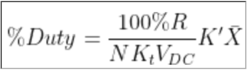
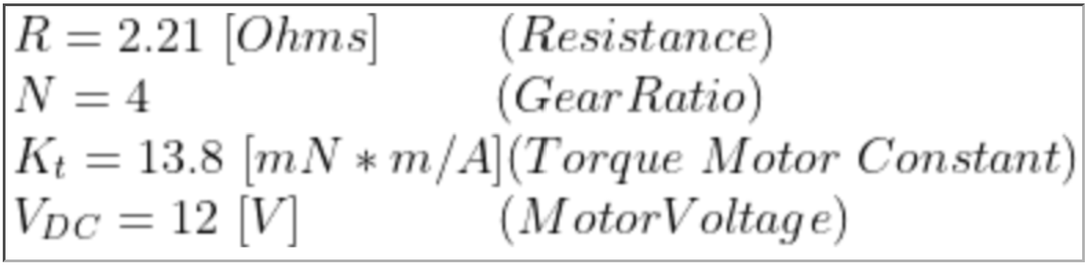
Where K' is the vector of K values described above and found in HW0x05, and the X vector contains the input parameters position, angle, velocity, and angular velocity. The constants in from HW0x05 were adjusted quite a bit to fit the system in the real world. This is likely due to a variety of factors including: unideal motors, inaccuracy in angle and position measurement, small timing errors leading to small differences in velocity measurements, friction, and other factors not taken into account in the theoretical system model.
The Scheduler, main.py, defines tasks for each of the above segments (TouchPanel, Motors, Encoders, and the Controller).
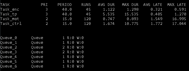
The Encoder and Touch Panel tasks are fairly straight forward - they update position and angle respectively, and then save it to a shared queue so that the other tasks may access it. The shared queue is provided by task_share.py. The Controller Task creates two instances of the Controller class using specified K values, one for each direction, and then uses the data from the Touch Panel and Encoders to get a duty cycle, which it also adds to a shared queue. The Motor Task then runs and sets the motors to the correct duty cycle. The tasks are set so that the Encoder and Touch Panel tasks run once every 40 ms, and the other two tasks run once every 15 ms. A list of scheduler tasks and shared queues and their descriptions is shown below.
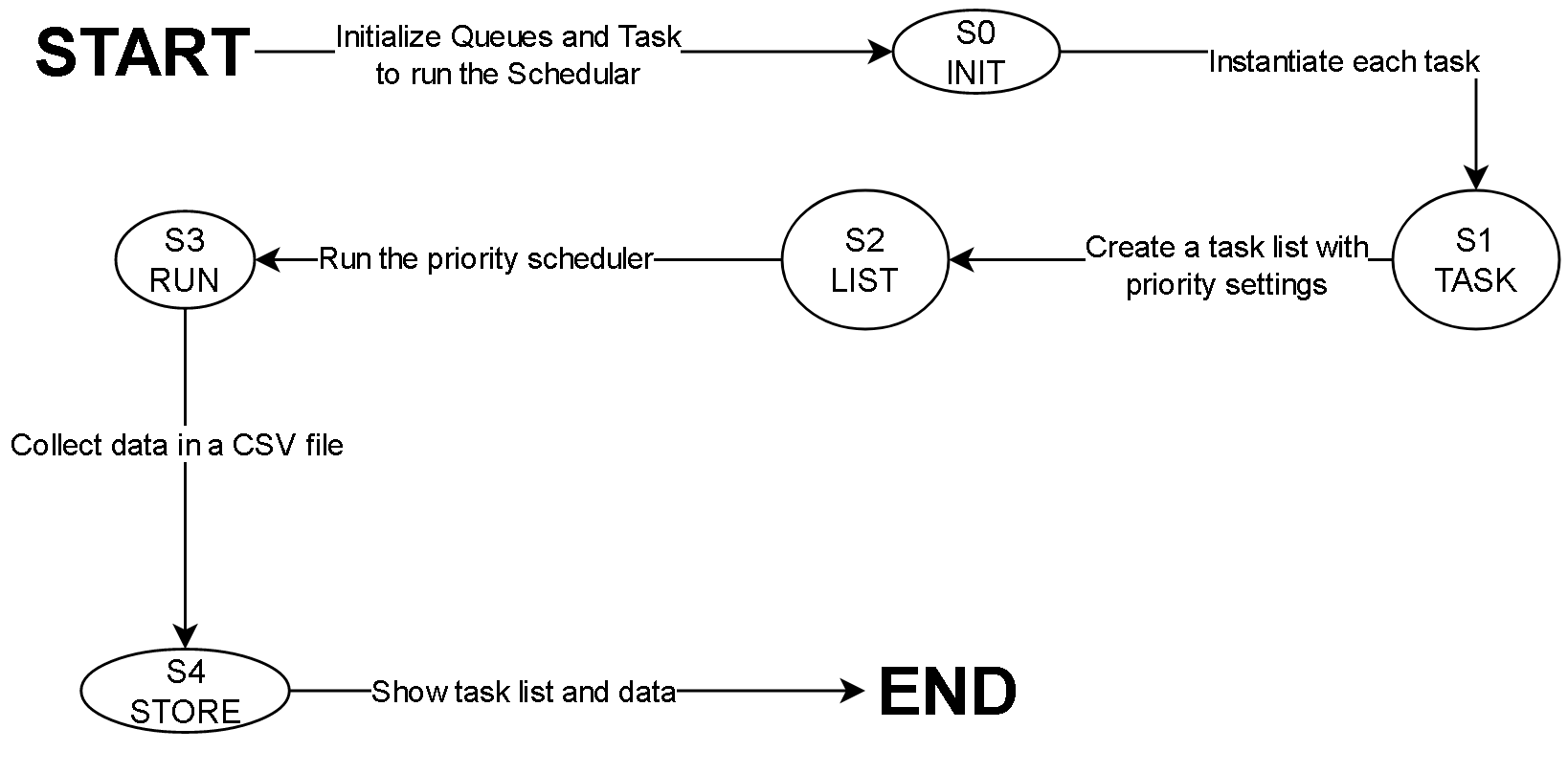
The state transition diagram for the project is shown below.
Neil's working platform is demonstrated below. The video contains a brief explanation of our procedure:
Neil's platform is a fair bit better at balancing the ball, and keeps steady while the ball is placed. It then moves the ball to a spot close to the center, though it does not get to the exact center.
Craig could not demo the project on his own hardware, as he accidentally broke his board (see Board Issues). This is the last recording of his still working platform:
While Craig did not have enough time to fully finish tuning his program, the platform clearly reacts to the touch and slowly moves back to equilibrium, though it somewhat overreacts due to its not optimal constant values for the controller.
Sample data taken during this process can be found in Documentation. Each .csv file has counts in the first column. To get to time, multiply by the period of Controller, or 15ms per entry. The second column includes the actual measurements. Data was not all from the same run. Data naturally varies from test to test, depending on ball placement, so this data does not reflect what would occur every time. The data of x and y positions are plotted below:
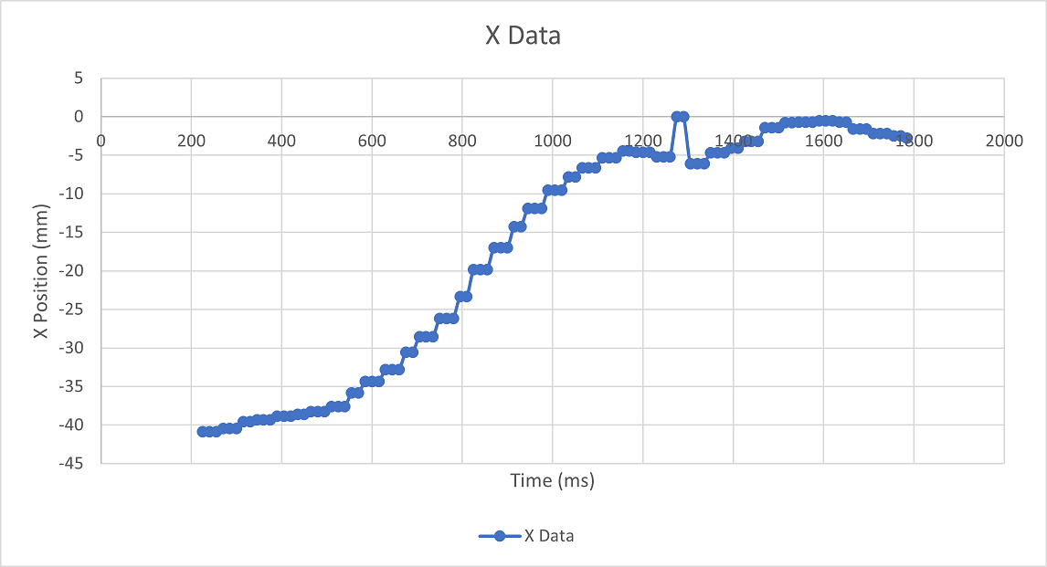
The X position of the ball started a little over halfway to the edge of the touch panel, at -40 mm. From there it is quickly balance to close to 0 mm, before over correction causes it to roll a bit further away. At time 1275 ms, the touch panel seems to have a small error and defaults values to 0. Luckily this is quickly corrected and the ball continues moving in the right direction.
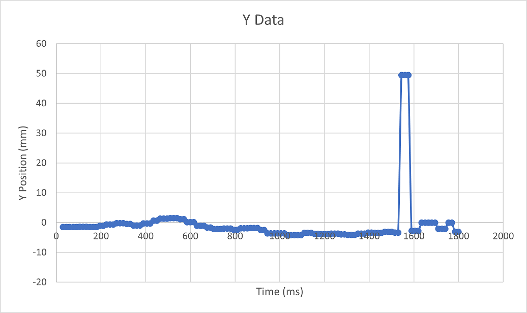
Similar to the X data, the Touch panel gives a couple incorrect data measurements for the Y position around 1550 ms in. The 50mm measurement was probably caused by detecting the ball, but having the ball lose contact with the panel before sensing its location. As a result, it detected the ball in the furthest position. For the most part the ball started fairly close to the x axis here, so little correction was needed.
A fair few problems cropped up, especially when putting everything together:
The touch panel had a few problems. The most concerning was a flaky connection along one of the wires connecting it to the microcontroller board. This resulted in the panel occasionally losing connection and giving completely false data until the wire was readjusted. This error came and went, so was left unresolved since the panel still worked fine most of the time.
Another major difficulty was the inaccuracy of the touch panel. The readings at either border were not always consistent - while measurements were fairly accurate nearer to the center of the panel (after calibration at least), the non-linear resistance of the device made measurements less accurate the further out you went. The border was also not exactly at the edge of the panel - touching the panel right on the corner gave nonsensical data. This problem gave problems for the controller, since it relied on accurate data to decide on a torque for the dc motors. Putting the ball too far from the platform made the measurements too inaccurate to work.
One last issue of note, which is fairly amusing looking back, was when a very small sticker somehow attached itself to the side of the panel. This resulted in the panel identifying a touch on that edge, and many, many hours were spent trying to determine the cause. This issue disappeared when the sticker was noticed and removed.
The Motors worked fairly well, and PWM was relatively easy to implement. The biggest problem stemmed from the two motors having different torques at the same power. One motor was significantly weaker than the other. This was likely just due to a manufacturing difference, since they are the same model of motor. However, it created problems for the controller, as it needed to be adjusted so that one motor wasn't running much harder than the other.
Another problem encountered with the motors was that the shaft was too loose for the platform arms, which led the motor to spin in place without moving the arms at all. There were three fixes for this problem - tightening the screw on the platform arm,, super-gluing the the shaft to the arm, and somehow filling the space between the shaft and the arm. Tightening the arm was out of question since the heads of the screws were messed up, probably due to previous usage. The other two options were pretty terminal (if you chose them, it would take some time to undo and redo in case of any backtracking). Ultimately, Neil decided to put some tape on the motor shaft so that the arm-shaft connection is tighter and actually moves the platform.
The encoders worked quite well from the start, however, the original implementation only handled overflow and not underflow. This created some odd data before the issue was resolved. There was also a question of an issue with accuracy as the belt tying the motor and the encoder would sometimes slip, but this issue seemed negligible.
The scheduler was easily the hardest part to get working, and as this is written, is still not fully operationsal - it still lacks a proper UI. It does manage all the tasks well and they all run quickly and at the appropriate time. There were some issues with using too small of a period for the tasks, which caused them to be unable to complete on time. This was resolved by increasing the time each task would run for. The biggest problem with the scheduler was trying to get the correct K constant values. No matter how they were adjusted, they didn't seem to work.
On Craig's board, a screw came loose and fell onto the MCU board. This caused a short between two pins - it even gave off a slight spark - and the board stopped working. Even replacing the Nucleo board with a new one did not resolve the issue, and the voltage at various pins was incorrect - so some damage must have been done to other components as well. This prevented Craig from getting the project running on his own hardware.
Documentation of this lab can be found here: Lab0xFF
A copies of the CSV files can be found here: https://bitbucket.org/npatel68/me405_labs/src/master/labff/collectedData.csv
https://bitbucket.org/npatel68/me405_labs/src/master/labff/xData.csv
https://bitbucket.org/npatel68/me405_labs/src/master/labff/xDotData.csv
https://bitbucket.org/npatel68/me405_labs/src/master/labff/yData.csv
https://bitbucket.org/npatel68/me405_labs/src/master/labff/yDotData.csv
The source code for this lab:
https://bitbucket.org/npatel68/me405_labs/src/master/labff/controller.py
https://bitbucket.org/npatel68/me405_labs/src/master/labff/encoder.py
https://bitbucket.org/npatel68/me405_labs/src/master/lab4/main.py
https://bitbucket.org/npatel68/me405_labs/src/master/labff/motor.py
https://bitbucket.org/npatel68/me405_labs/src/master/labff/touchPanel.py
The repositories of the students involved in this project can be found at:
https://bitbucket.org/npatel68/me405_labs/src/master/
https://bitbucket.org/cbelshe/me405_craigbelshe/src/master/